
By John Logan, May 1997
Several people have asked for more information on the fulcrum pin reinforcement that that they have seen on my Tiger and that I briefly described during the technical session at the Orlando United XVIII.
Why should we be concerned? There has been a lot written about the weaknesses in the basic design of the front suspension of the Alpine and Tiger as well as some of the aftermarket parts, so I won’t go into the reasons again why you should be concerned. However, I will add one more condition that I haven’t heard much mention of. Here in Michigan we have the high damaging loads from broken roads and potholes. Some of you that attended United XVII commented on the condition of our roads and that was after our spring repair. In the winter of ’95, a deer got trapped in a pothole near Detroit. After getting hit, flattened by passing cars and frozen, a patching crew came by and covered him up. When spring came of course he began to swell and blew the patch out for all to see. You may have read in your papers about the lawsuits that followed. Well, so much for why!
What is the modification? I’m going to describe only an improvement to the fulcrum pin and its attachment to the front crossmember, suitable for “street vehicles”, since there are many adequate solutions to the other front suspension problems. See Pic 1. The modification consists of a 1″ square structural tube running parallel to each fulcrum pin that is welded to the bottom face of the crossmember. See Pic 2. Each end of the tubes are connected with links to each end of the Fulcrum Pin.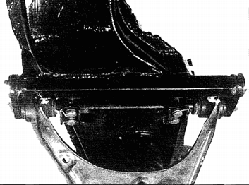
Why does it work? Because of the relative stiffness of the added tube, approximately 75% of the loads that are generated from braking, cornering and wheel movement. Damaging loads are transmitted by links attached to the fulcrum pin impacts are transferred directly to the tube through the links. Thus the stress that can causes fatigue failure of the fulcrum pin, the four small attaching bolts and the welded tapping blocks is reduced by 75%. Those of you familiar with the laws of material fatigue will recognize that, considering previous failure history, the redesign should provide infinite fatigue life of the assembly. This redesign also provides a redundancy by being able to support the lower control arm in the event of an accident.
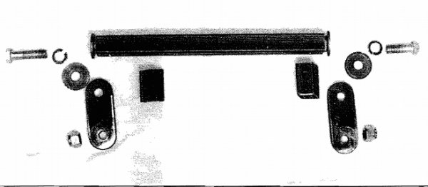
I realize this is not an easy job, but it eliminates a lot of worry when you or your loved ones drive your car hard or a long way from home. New parts consist of the structural tube, load transfer links, reinforcing tube assemblies, bolts and washers.
Building the added parts:
- The main tubes are made from 1″ square structural steel tubing approximately 12″ long. The exact length will be determined at step 3 of the welding sequence. After determining the length, drill four 1″ puddle weld holes, in each end of the tubes 1″ from the ends.
- Use 2″ x 1″ x 20 wheel nuts for the threads in each end of the tubes. Grind two opposite corners of the nuts so that they fit inside the tube and weld a heavy washer squarely on each nut. Because of a lap joint in the bottom of the crossmember a section of the face of the tube must be removed and fitted to allow the tube to sit flat. See Pic 3.
- Two short tubes are made from 1″ tubing long enough to run from the main tubes to the welding flange of the crossmember. These pieces are not the same length so measure each of them individually. After they are cut they should be shaped into a trapezoid to match the surface of the crossmember.
- The links are made from 4″ X 11″ X 3″ steel bar stock. Drill two 1″ diameter holes on the centerline, 21″ apart and radius the ends of the links for appearance sake. If you are drilling these links by hand, mark them so that they can be reassembled in their proper position later.
- Use two 1″ X 20 grade 5 or 8 bolts long enough to have a shoulder for the links but not long enough to bottom out in the welded nuts.
- Use four 1″ heavy lock washers on the bolts.
- The nuts shown are the original prevailing torque nuts from the fulcrum pin.
Welding Sequence
1. Remove the front suspension from the car unless you or your welder are good at welding upside down in tight places. The fulcrum pin and lower arm do not have to be removed.
2. With fulcrum pins bolted in their normal position and tightened to 40 ft/lb, remove the nuts and washers from the ends. See Pic 4.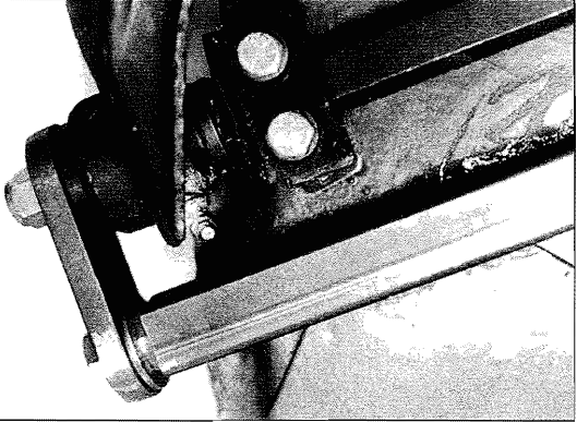
3. Assemble the links, and attaching bolts and washers with the wheel nut and washer weldments inserted into the tubes. The final length of the tubes are determined at this point. Allow about 3″ gap between the washer and the end of the tube for welding. The fulcrum pin nuts must be tightened until the links bottom out on the inner sleeve of the suspension rubber bushings. If you are using neoprene bushings, then the links should bottom out on the outer shoulder of the fulcrum pins with clearance for the lower arm to move. Center the tubes on the wheel nuts and clamp them to the crossmember.
4. Tighten the bolts. The length of the tube assembly is now determined by the links so that you can tack weld the nuts to the tubes on two sides.
5. Now remove the tubes and weld the ends including the puddle welds.
6. Reassemble the tubes in their original position and clamp them to the crossmember. The links now serve as a fixture to locate the tubes.
7. Tack weld (TIG or MIG) the long tubes, tack the short tubes to the assembly and finish weld all tube edges to the crossmember.
8. Paint and install the crossmember on your vehicle.
9. Tighten the 1″ bolts and fulcrum pin nuts to 65 ft./lb. This step is important! In order for the links to transfer the loads to the new tube, the link holes must fit tightly, the links must seat squarely and the bolts must have the proper torque. If you have rubber bushings, the full vehicle load must be on the wheels before tightening, to index them to their neutral position. Standard width Ford 260 to 302 oil pans in Tigers will clear the new inboard links. If you have a wide pan, you better check. Also I am not familiar with the clearances required for Alpine engines.
For more information, contact John Logan