by Andy in the May 1995 RootesReview
One of the subjects that tends to be a black art to many people is setting up the Alpine steering system. Admittedly, if you dismantle the steering and suspension assembly on your car then you have to be very careful about what you do and how you go about doing it if you are not to run the risk of upsetting the steering geometry.
Most people, however, only wish to check that the front wheel alignment is correct. This is a fairly easy task which does not need expensive test equipment providing you follow a few basic rules.
If you intend to get your Alpines’ front wheel alignment checked by someone else, then beware where you take it as many establishments, especially those where the main business is tyre fitting, are not used to adjusting steering systems such as that fitted on the Alpine. This is because virtually all modem cars are fitted with rack-and-pinion steering, a much simpler steering system. It is not uncommon for such establishments to cut corners or make mistakes when carrying out adjustments to our type of car. The end result of this is usually that your front wheels are aligned when in the straight ahead position, but that your steering geometry has been ‘messed up’ when the wheel is turned in either direction. This can result in increased tyre wear.
One of the most obvious ‘indications that your steering has been ‘got at’ is where you find that the steering lock is greater in one direction than the other. Sometimes this difference can be quite considerable and in extreme cases can make the car quite dangerous to drive. In almost all cases this fault is entirely due to a previous maladjustment of the track rods whilst adjusting the front wheel alignment.
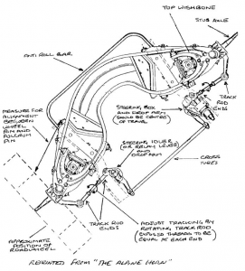
If you wish to set the alignment on your car or your steering turning circles are unequal then the following procedure may come in useful. Basically the procedure is that described in the Rootes workshop manual, but adapted to Do-It-Yourself (DlY) techniques and tools. In the Alpine Guide, Chris Barker describes an excellent way of constructing a DIY steering tracking measurement device. You will need to construct one of these and you will need a steel rule and your trusty toolbox to be able to carry out this check.
- Firstly, drive the front wheels up onto suitable ramps, keeping the steering in the straight ahead direction as far as possible and securely chock the rear wheels to prevent the car rolling off. This will allow access to the steering track rods whilst allowing the steering and suspension components to remain fully loaded.
- From under the car, slacken the inner and outer ball joint lock nut on each track rod. With a suitable ball joint splitter, disconnect both inner track rod ball joints from the steering drop arms.
- From inside the car, move the steering wheel to full lock in one direction, and mark the wheel with a suitable length of sticky tape. Using this marker, count the total number of full and part turns from lock to lock; divide this by 2 to achieve the steering box central position. Move the steering wheel to this position and re-mark with another suitable length of tape. The steering wheel now must not be allowed to move from this position until the whole following procedure has been carried out. Tie in position with a suitable length of cord if necessary. (Note: If your steering wheel spokes are not central then do not adjust the wheel at this point).
- Count the number of exposed threads at each end of the O/S track rod. If they are unequal then adjust one of the track rod ends until the number of inner threads equal the outer threads. Do not disconnect the outer track rod ball joint whilst carrying out this task and note that the inner and outer threads are handed differently – this is to allow you to adjust the track rods without disconnecting the ball joints, the procedure for which we will come to in a minute.
- Carry out the same procedure (4) above for the N/S track rod. Note that the total number of threads need not equal those on the O/S.
- From the front of the car measure the distance from the each front wheel inner rim to the lower wishbone inner fulcrum pin. If the distances differ then move one of the wheels until they are the same. Accuracy in measurement is vital at this point.
- From under the car, adjust each track rod in turn until the inner ball joint pin can be located in the drop arm. DO NOT MOVE EITHER WHEEL OR DROP ARM AT THIS STAGE. To keep the number of threads exposed at each end of the track rod equal, the rod should be adjusted by turning the rod whilst holding the inner ball joint stationary. When the rods are of correct length, locate the inner ball joint pins in their drop arms and lightly tighten the securing nuts so that the tapers are fully home. Mark the track rods at the 6 o’clock with a blob of white paint.
- From the front of the car, recheck that the measurements taken in (6) above are equal. Measure the front wheel alignment with a suitable device such as that described in the Alpine Guide. This is done by measuring the distance between the outer rims of the front wheels, both at the front and the rear of the wheel, subtracting the difference between the two and halving the resultant amount. If the measurement between wheels is less at the front than the back then the wheels are ‘toe-in’ and if the measurement is greater at the front than at the back then the wheels are ‘toe-out’. The correct normal wheel alignment for the Alpine is 3mm ‘toe-in’ measured at the periphery of the tyres. This can be equated to a figure of approximately 2mm ‘toe-in’ measured at the wheel rims. To achieve the correct toe-in, the track rods must be rotated an equal number turns and they should both be rotated in the same direction. Use the white painted marks as a guide on rotation and note that the ball joints must not be disconnected.
- When the toe-in has been set to the correct dimension, then make a final check as in (6) above. Tighten the track rod lock nuts and the inner ball joint pin lock nuts. Lastly, reposition the steering wheel if necessary so that the spokes are at the ‘quarter to three’ position.
Finally, note that when the steering is properly set up that the free lengths of the two track rods are likely to differ. This is entirely normal and no effort should be made to make them equal.
